First angle and third angle projection methods are widely used for the representation of engineering drawings. A collection of 2D drawings of any 3D object is represented with the help of orthographic projection. The orthographic projection consists of 6 views (Front, Back, Top, Bottom, Right, Left) called as principle views. Among these six.. 1.6 First and Third Angle Orthographic Projection Symbols. Standard Symbols. Recommended Proportions for symbols: The symbols for first and third angle are based on the frustum of a cone as shown. Frustum of cone in the first quadrant: First-angle projection; View from the left appears on the right.

Symbols For 1st And 3rd Angle Projection Design Talk

PPT Orthographic Projection PowerPoint Presentation ID466828

How to draw First angle projection symbol YouTube
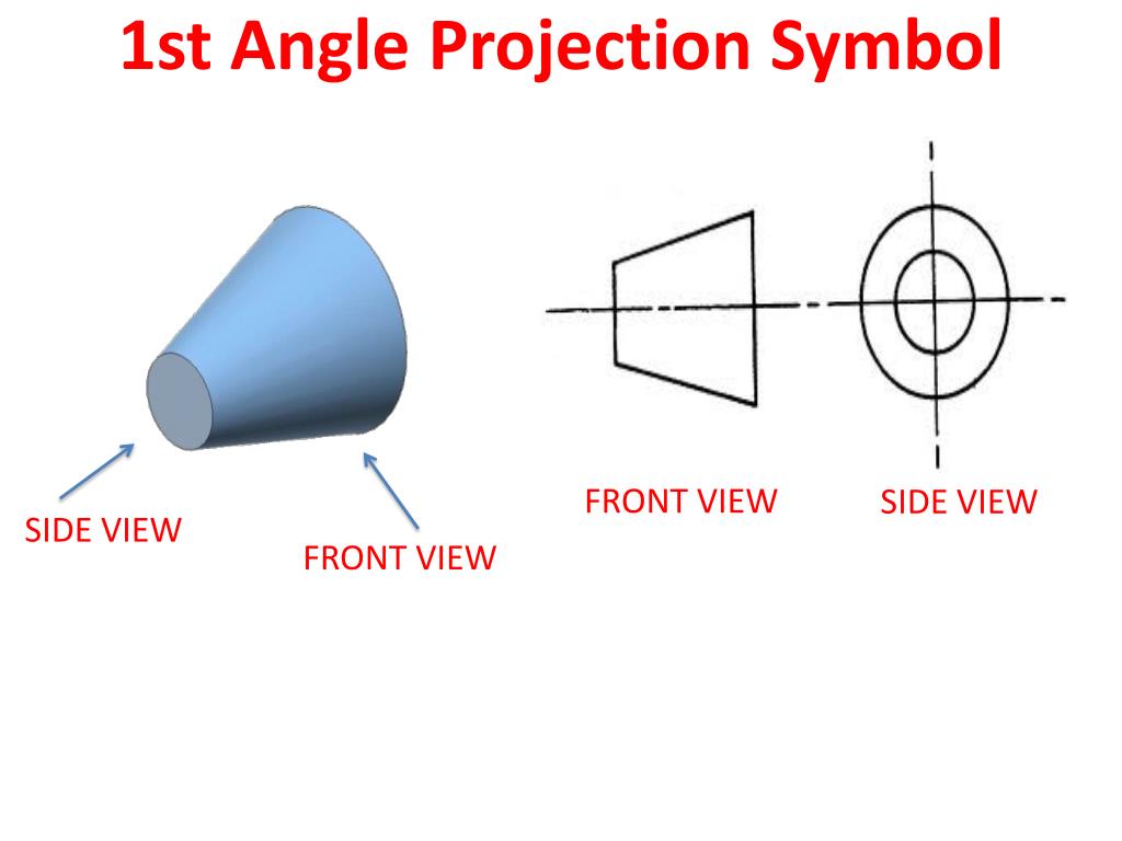
PPT Technical Drawing CHAPTER 1 PowerPoint Presentation, free download ID2663439

First Vs Third Angle Orthographic Views Gd T Basics vrogue.co

First angle orthographic projection notes

First Angle Orthographic Projection Symbol

First Angle Projection Symbol YouTube

First Angle Projection vs Third Angle Projection

Symbols of 1st & 3rd Angle Projection as per ISO specification//First and third angle projection

1st angle and 3rd angle projection symbol first angle symbol symbol Engineering Drawing
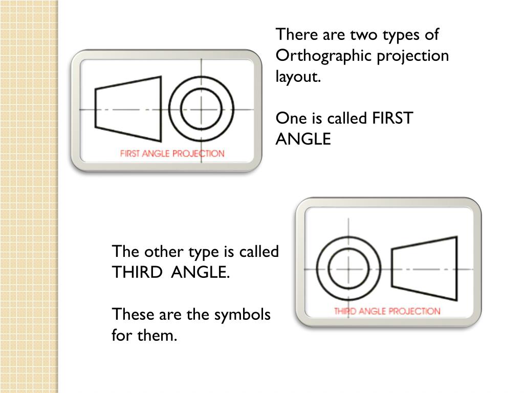
First Angle Orthographic Projection Symbol

Difference between first angle and third angle projection

Symbol Difference 1st Angle & 3rd Angle Projection By Surender Sharma YouTube
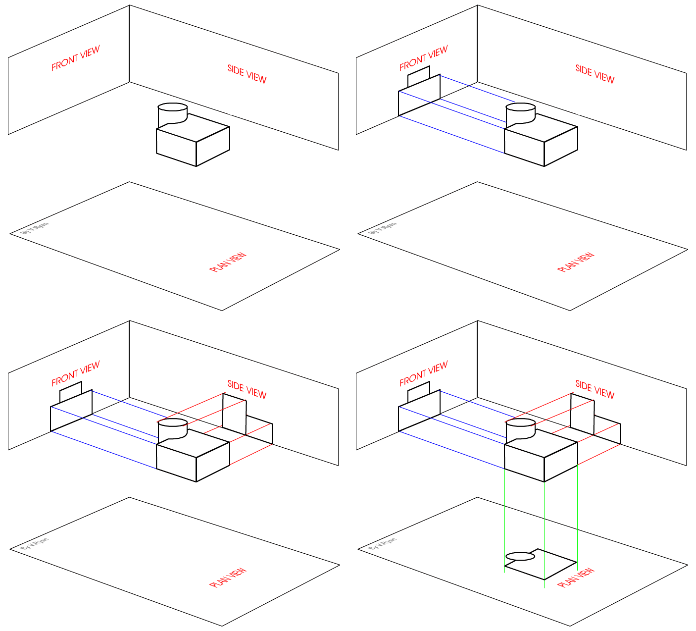
First Angle Orthographic Projection

FIRST ANGLE PROJECTION METHOD YouTube
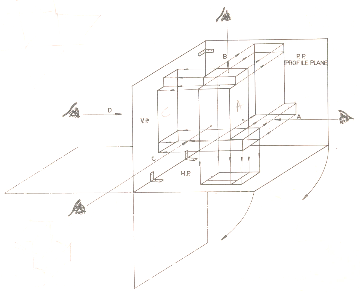
Basic Engineering Drawing Projection Knowledge Zone, The Online Support

First Angle Orthographic Projection Symbol
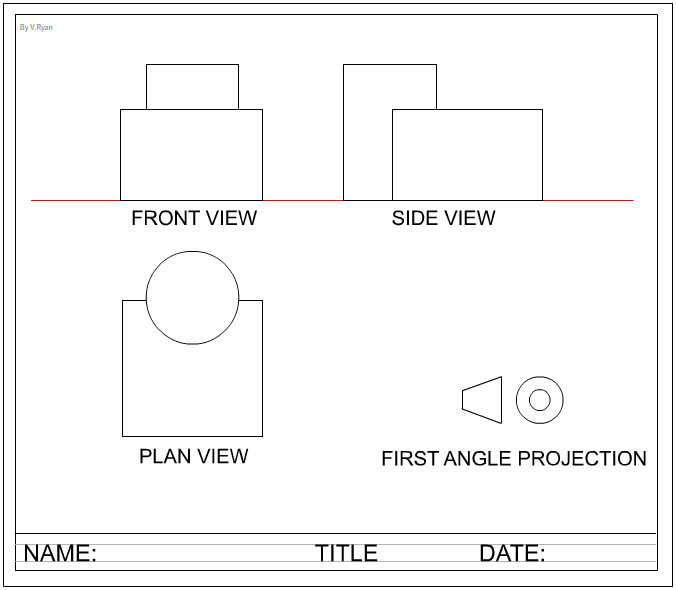
First Angle Orthographic Projection

Build A Tips About How To Draw First Angle Projection Originalcurrency
-first angle projection, used in the rest of the world. So far we have only looked at third angle projection, since this is used here. Figure 3.1.7 shows a part in third angle projection, Figure 3.1.8 shows the same part in first angle projection. To avoid confusion, drawings must be identified by means of the symbols shown in Figure 3.1.9 as.. In first angle orthographic projections the object is considered as being rolled over to either side, so that the right side of the object is drawn to the left of the front elevation: It is mandatory to indicate the method of multiview projection by including the appropriate ISO (International Organization for Standardization) projection symbol.